Category: Project

Eagle ULP script for double sided PCBs on a CNC

For the past few months I have been working on and off on a ULP script that would allow for double sided PCBs on my home CNC machine. The script is 95% finished and I have been using it for a while. I recently ran into an issue where my older 5.x license of Eagle PCB was causing problems with the latest 7.x version of Eagle. Because of this I am trying to Kickstart an upgrade of my Eagle license in return for access to my ULP script that allows for double sided PCBs on a CNC, as well as allowing for non-square shapes.

Take a look at the campaign here: Eagle PCB update for CNC Double Sided PCBs

s1axter

Home CNC breadboard power adapter

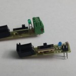
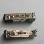
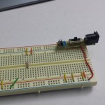
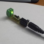
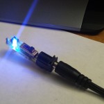
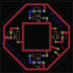
One really nice thing about having a CNC to make PCBs at home is the ability to whip up a quick adapter board in one night. Tonight I needed two adapters for a 5.5mm barrel jack, one to go to wires and one that can plug into a breadboard. Eagle allows you to make a board without a schematic which is exactly what I needed, just draw some traces on copper and route it out on the CNC. I used 40-60 mil traces and slapped on random switches I had laying around and an LED with resistor. The boards came out to be about 1.75″x0.4″ and routed perfectly with a 0.8mm router bit. I uploaded a zip with the Eagle board files and G-Code for anyone else who wants them.

bb_jack.zip – Eagle files and G-Code

s1axter

Portable PIC development kit

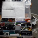
Lately I’ve been moving between 3 different locations and have been trying to do contracting work related to PIC processors. It was really frustrating to have all my development tools and components only at my home office when I was away so much. The solution was to add what I needed to one portable kit to take from location to location. My first attempt was a small plastic toolbox, but that was quickly filled and always seemed to be a mess. Next I tried a plastic shoebox from home depot for $0.99. This worked well since I could see everything that was in it, however it was a pain to carry around since there was no handle and it didn’t fit into a bag nicely. The solution I came up with was a plastic parts bin with moveable seperator walls, like you can find a Harbor Freight or Home Depot. With the movable walls, you can really cram a lot of stuff into them, I was impressed with everything that I got into the bin.

  • 3 pencils
  • 1 pen
  • 6 DIP PIC micocontrollers
  • 1 DIP EEPROM
  • 1 character LCD
  • Double sided tape
  • Wire cutters
  • Spade cutters
  • Plyers
  • hobby knife
  • super glue
  • velcro squares
  • 23 row breadboard
  • Bus pirate
  • Bus pirate cable
  • Tweezers
  • 2 Antistatic bags
  • Electrical tape
  • Alligator clip wires
  • Jumper wires
  • 3×2 programming wire
  • Micro USB phone cable
  • A to B USB cable
  • Voltmeter
  • 5 PIC Microcontroller dev boards
  • 2 Prototype backboard
  • 1 9v packboard
  • 2 crystals
  • USB to serial adapter
  • Serial adapter cable
  • Serial adapter
  • 4G USB drive
  • Mini philips screwdriver
  • Mini flat blade screwdriver
  • Medium dual head screwdriver
  • PICkit3
  • 2 Mini USB cable
  • FTDI TTL serial cable
  • 4 port Mini USB hub
  • AC USB adapter
  • AC 12v adapter
  • USB to 5.5mm barrel jack connector
  • 9v battery to 5.5mm barrel jack
  • 2 Barrel jack breakout boards
Electrical parts

  • Jumper wire
  • Misc pots
  • Misc caps,
  • Buttons
  • LEDs
  • Misc resistors
  • Regulators
  • Header
  • N-chan FETs
  • Misc diodes
  • Solder
  • Barrel jacks

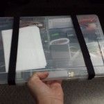
While the box does close and latch, I use two fabric hook and loop straps to make sure it stays closed.  The unit is really compact and fits in any backpack or side bag.  I do have a breadboard I take with me as well and I think I found a small plastic picture box that can hold that so I don’t crush components when it is in a bag.  Here are some pictures too

s1axter

Raspberry Pi – Cross Compile & Kernel

This is the first post in a series on getting down into the bits of a Raspberry Pi Linux installation. It assumes familiarity with the Linux build process, gcc, make, apt-get, ssh, etc.

Lately I have been thinking about a project that would require a beefy embedded system, one with embedded Linux, fast, and lots of storage.  It turns out the RaspberryPi has all the requirements for this project, and I have one laying around, so I figured I would pull it out and get a full development toolchain started to see what the little Pi could do. This project might require a Linux driver module, so for that I need to compile the kernel and modules too. All steps were done on an Xubuntu 12.10 32-bit machine with the Ubuntu GCC/binutils/make packages installed.

Image

The first step was getting an image running.  I tried a few and the Arch Linux image is prefect for an embedded project, it doesn’t contain all the X crap by default, it boots  in ~10 seconds (thanks to systemd) and the stock image only takes up about 450Mb on a flash drive, leaving lots of space.  Here is the image (I used the version from Nov 2013), here is how to make an SD card.

Toolchain

The next step was to get a cross compiler toolchain build.  I have seen a lot of posts that say “do an apt-get install gcc-arm-linux-xxxxx on Debian”, that’s all well and good if like relying on Debian, I would like full control over my toolchain, and I don’t want to have to export tons of bash variables for tool locations.  Fortunately, there is an awesome application called crosstool-ng that makes downloading and building a custom compiler and tools a breeze.  I followed this post successfully and put the output directory of the cross compiler binaries within my home directory, this way the ARM compiler isn’t system wide and I can move it where I want it.  I did have to install some packages “sudo apt-get install gperf texinfo gawk libtool automake libncurses5-dev”. The test application compiled without issue and a quick SSH got me “Hello world” on the Pi command line.

Kernel

Rebuilding the kernel and modules seemed a little daunting, but actually it’s pretty easy once you do it. These two references (PDF and elinux) were good for understanding the process.  The kernel for the Raspberry Pi is build from a central git repo, so you just need to clone the repo and you have the whole kernel source all patched and ready to go.

The Arch Linux build has a handy feature enabled, it outputs the kernel config for the running kernel in the /proc directory, which means if you use this config as the base for your config, all the settings match the current kernel, which you know works. Copy the file /proc/config.gz from your Pi, uncompress it to ‘.config’ in the root of your kernel source and it will be read by menuconfig, can’t get easier than that!

Now, because I compiled the toolchain into a local home directory I need to pass the path to it for each call to make.  This isn’t that bad because I plan on making scripts that build the kernel and modules whenever I need them.  Here is an example of how to run menuconfig and the final make:

make ARCH=arm CROSS_COMPILE=/home/s1axter/raspi/toolchain/arm-unknown-linux-gnueabi/bin/arm-unknown-linux-gnueabi- menuconfig
make ARCH=arm CROSS_COMPILE=/home/s1axter/raspi/toolchain/arm-unknown-linux-gnueabi/bin/arm-unknown-linux-gnueabi-

The kernel make builds both the kernel and the modules for that version of the kernel.  You have to copy over both the new kernel and the kernel modules since you can’t use the old modules that exist on the Pi.  Again, rather than export a bash variable like the elinux source says I pass the module folder path in the make command.

make modules_install ARCH=arm CROSS_COMPILE=/home/s1axter/raspi/toolchain/arm-unknown-linux-gnueabi/bin/arm-unknown-linux-gnueabi- INSTALL_MOD_PATH=/home/s1axter/raspi/kernel/modules

After these build steps use sftp or some other means to get the modules and firmware directories in the ‘modules/lib/’ folder into the ‘/lib’ folder on the Pi. The kernel new image is ‘arch/arm/boot/Image’  from the kernel source folder and needs to replace /boot/kernel.img on the Pi (Make a backup, just incase).  I used scp/sftp, so I logged into the Pi and did a ‘sync‘ command to make sure everything was written to the SD card and then ‘reboot’.  I might have been lucky but the Pi came back up and my kernel went from 3.10.18 to 3.10.25!

Good luck
 

GoPro timelapse ffmpeg

So I got a GoPro this Christmas for skiing.  Yesterday I took some footage on the mountain, including some time lapse shots which I wanted to stitch together to make a sped-up video.  I’ve used ffmpeg a bunch, so I knew it could do the job.  There isn’t much to making a movie from the images, and the following command works pretty good.  The only tricky part was the GoPro doesn’t start all timelapses at G0020001.JPG, mine was at G0020069.JPG. The timelapse setting was one picture every 0.5 sec and the output is 10 fps.  The GoPro still are also 4000×3000, so I convert them to 1920×1080 to match the video frame size, this adds a little distortion but still looks pretty good.

ffmpeg.exe -f image2 -r 10 -start_number 69 -i G002%04d.JPG -vcodec libx264 -pix_fmt yuvj420p -s 1920×1080 out.mp4

The 10 fps had some weird conflicts with my editor, so 29.97 fps might work better.

Nixie test

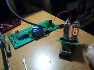
Here is a short video of the nixie tube clock with the first nixie tube connected.  The controller board uses a PIC24FV32KA302 processor, a 74HC595 shift register, a 74LS374 octal latch and 74141 driver chip to control an IN-14 nixie tube.

Check back for more on the clock.

Nixie boards

So the nixie boards are in.  I used iTeadStudios from China to make a few daughter boards that hold 2 nixies, 2 74141 driver chips and a 74LS374 octal latch.  Using a 374 latch and the 74141 chips allow me to write an 8-bit value to the boards and latch it in.

The boards are 5cm by 5cm and cost <$2 each from iTead since I got 10. Shipping took about a month, so if you plan on using them, plan accordingly.

The daughter boards are attached to a controller board with a PIC24FV32KA302 micro and a 74LS595 shift register.  The controller was made by Advanced Circuits here in colorado and came in today after about ~5 business days. I have to say it is probally my best board ever, guess all this practice is paying off.  I did make a few mistakes, including routing the nixie board connector backwards, which means some hacked connector pins. Good decisions PCBs come from experience, experience come from making bad decisions PCBs.

Controller schematic

Daughter boards (I forgot to add 5V to the connector, so that is a blue wire)

Linux controlled CNC!

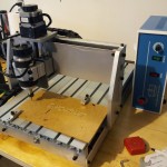
So the magic box contained a 3 axis CNC! Very very cool.  I have made PCBs for years, and have come to two realizations, chemical etching sucks with unreliable results and professionally made PCBs can take lots of time and money, especially for single prototypes.  I bought this CNC to make PCBs on demand and on the cheap.  I also plan on cutting basic plastic and metal parts, but mostly PCBs.

I purchased the unit from Ebay from the seller “igoodmart2011” for about $900 USD.  Here is a search for CNC 3040.  The one I purchased included the blue control box however does not have the water cooled spindle

Here are some specs for the unit

  • “No name” “CNC 3040” from China
  • 3 axis (X, Y, Z)
  • 300 x 400mm area (275 x 385 x 55mm working area)
  • Motors: two-phase 57/1.8A steppers
  • Repeat positioning Accuracy:0.05mm
  • Manual spindle control: 1000~8000RPM/MIN
  • Parallel port interface

The unit was shipped from LA and arrived here in Colorado in about 4 days.  The unit was mostly assembled in the box.  The frame and was assembled, the table the material sits on was attached and all cables and cable trays were run and attached.  The stepper motors were in a separate box and were attached without issue to the 3 axis shafts.  The controller box also connected up quickly as all cables were marked.  Attachment to the PC was done via an included parallel cable.

One thing to note, a DVD was included in the package, and when I tried to read it on a Windows machine it said it was blank.  If you plan on using the provided software on the CD make sure you can contact the seller to get a copy if the DVD doesn’t work.  I personally didn’t care because I am going to  control the machine via LinuxCNC, however a digital manual would have helped.

I’ll do another post explaining how to setup and control the machine.

Video blog – Time and Bitfield structs in micros

Bitfields: http://en.wikipedia.org/wiki/Bit_field

Source: MainloopDemo Code

4x4x4 LED Cube

A 4x4x4 LED cube using 64 LEDs, 2 74LS168 shift registers, 4 NPN transistors. Software written in C on the Mbed prototype platform

WordPress Themes