 Holy crap! Has it really been a year? Damn, I’m not good at this whole blog thing. Eh, well can’t keep a crazy engineer down, over the past year I have been working as an embedded engineer working on battery systems for hybrid electric vehicles, really cool stuff. For some of my other projects take a look at my site on electric and vegetable oil powered vehicles: http://thesmartdrive.com
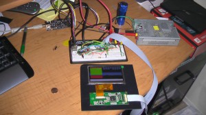
If you take a look at The Smart Drive you will see I have an electric car I built with friends and family back in 2001. A while ago the speedometer started to give out in it (hey, it is a 91) and I got the crazy idea of replacing the gauges in the dash with an LCD to show speed and cell voltage. This back burner project has started to get some traction and I wanted to share my endeavors with everyone else. Take a look at the full article!
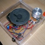
 After making the Standalone Voltage Regulator I decided to see what else could be made on one of the single IC boards from RadioShack. About a year ago I built a mini-guitar amp using an LM386 audio amplifier and a small 8 ohm speaker from an old computer, you can see the post on geeksinside.com. Since the LM386 only needs a few capacitors and a resistor I wanted to see if it can be crammed on to one of the boards. After a bit of study the answer is yes! This week I soldered the unit together and mounted it an acrylic box you can find at craft stores. I plan on doing a write up like the regulator, with part numbers and part layout, however for now I have a gallery up showing the finished product.
Here is a short list of the parts I used, for the ambitious:
- RadioShack single IC PCB
- 100 uF electrolytic capacitor
- 0.1 ceramic capacitor
- 4.7 uF capacitor
- 10 uF capacitor
- 10 ohm resistor
- 8 ohm speaker
- 25 ohm potentiometer
- 9v battery and snap
- 1/4″ mono phono jack
- LED
Here are a few links to simple amps using the LM386. LittleGem Amp CigarBox Amp
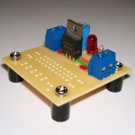
 This week I dug through my electronics box and realized one of those Dual General-Purpose IC PC Boards from RadioShack would hold a LM7805 and requisite Caps. and LED very nicely. After a bit of soldering I had a working unit. Rather than just keep my new unit to myself I did a detailed write-up on how you can make this standalone regulator using parts from RadioShack!
I am also excited to announce that I have partnered with C Code Systems to provide component kits for these boards! While you can go to the store and get all the parts (any good hackers should already have most of them) C Code Systems has put together kits that include all the parts required for the project. I think this would be great for an introductory soldering or electronics course! Visit the C Code Systems Product Page
Its been a while since I have posted anything here! As you can tell I’m not a real regular blogger but every now and then i get a little itch to do something. Today I present you with a tutorial on how to make panoramic photos on Ubuntu 8.10!
I have a write up with an example here: http://www.mybitbox.com/articles/panoramic-photos-in-ubuntu/

Take a look and make some cool pans!
Originally posted September 9th, 2008
I got the Esquire magazines today (2) and ripped one apart before even looking at the first page. I have to say I’m a little underwhelmed considering the E-Ink is only 2×5 inches and isn’t a matrix like I hoped :-(. However that underwhelmedness lasted only a few minutes until I discovered the whole thing was controlled by a PIC16F629 and there are connections for an ICSP connector!
A little about the setup, like the post on the Make blog said there are two panels that change shapes and text black then white. The top panel has 11 distinctly controllable cells with 4 blocks, 3 rectangles, “The 21st Century”, “Begins”, “Now”, and the space in between. I read a little today on how eInk works and it doesn’t surprise me they made distinct blocks, an addressable matrix seems complicated.
Tonight after work I soldered some wires onto the controller and downloaded and disassembled the firmware. Â I was a little surprised there was no Code Protection enabled. It’s all PIC asm so it’s going to take some time to decode/modify, however expect some different animation sequences.

I’ve decided to not post the code since it is copyright to Hearst Media or the engineer who wrote it. If you want to pull the firmware here’s how:
- Get/borrow/make a ICSP programmer (parallel programmers will work, just lead out the Vdd,Vss,MCLR,CLK,DATA pins
- Remove the battery since it is only 3v and most likely you will be using 5v
- Hook up the programmer and read the HEX (Code protection is NOT enabled)
- Disassemble the code using your software of choice (mine is PikDev and gpasm)
I uploaded a new album to the gallery with some photos, take a look: mybitbox.com/gallery/esquire_eink/
If you have any questions leave a comment here, on Geeksinside.com or talk to me on EFNet #geeksinside
So here is a little update. After doing the trackbot I started to think of some other projects that I’ve been wanting to do for a while. While there are HUNDREDS of ideas floating around up there, one was doable and would look really cool and that is an RGB lamp of some sort. I remember seeing this project: www.electronics-lab.com/projects/games/005/index.html and really wanting to do it. So last week I scoped out some PICs on the Microchip site that have PWMs and ordered some samples. Also I got on ebay and bought a 3W RGB LED, and here is the best part…I had a paypal gift card so it didn’t cost anything, always a plus  For those less fortunate the LED is ~$10, kinda like this EBay Listing.
Today I got my PICs, one each of 16F737, 18F2220, 18F2680 and 16F88. They should work with my linux based setup. I’ll post some pics of the setup soon but if you want to just know the facts I am using Ubuntu 8.04 with PikDev (pikdev.free.fr/), gputils (gputils.sourceforge.net/) which can be installed via Synaptic, and my P16PRO knockoff parallel programmer (geeksinside.com/view/180/Parallel-Pic-Programmer/). The dev is done in assembly right now, but that’s why I got the PIC18Fs, so I can try out the PikDev C compiler and maybe even SDCC (sdcc.sourceforge.net/).
That’s it for now, I plan on making myBitBox a real personal blog, so check back!
Update (Sept. 3rd): I started a gallery of the RGB Lamp, I plan on updating it over time. Here it is: Http://mybitbox.com/gallery/rgb_lamp/
Last week I picked up a Tamiya tracked vehicle cassis from a hobby store to use as a mobile platform. http://www.superdroidrobots.com/shop/item.asp?itemid=484
Sunday and Monday I put it together and canibalized my old Hookbot for the H-Bridge, gearboxes and PIC. I used the Tamyia dual gearbox drive rather than the one that came with the chassis because any good robot can turn, not just go forward and reverse; hey maybe I’ll use the single motor for a turret! Anyway the brains are a PIC 16F872 and the H-bridge is a SN754410. The drive motors are power by three AA batteries for ~4.5volts and has a bit of acceleration and power, I am quite impressed. Right now the H-bridge gets a little warm when the motors are strained. I am going to have to do some tests and see how hot it gets on carpet running for a few minutes.

Here are some pics!: http://mybitbox.com/gallery/trak_bot/
Old Hookbot code (pretty much the same): http://mybitbox.com/files/s1axter/hookbot.asm
And a Video: http://www.youtube.com/watch?v=CJphi2-PTYU
Today I added myGallery to the files section of the site. This version will run from any directoy on a webserver, just upload JPGs and run convert.run. Here is the link: http://mybitbox.com/files/s1axter/mygallery.tgz; it is TARed and GZIPed.
 Holy crap! Has it really been a year? Damn, I’m not good at this whole blog thing. Eh, well can’t keep a crazy engineer down, over the past year I have been working as an embedded engineer working on battery systems for hybrid electric vehicles, really cool stuff. For some of my other projects take a look at my site on electric and vegetable oil powered vehicles: http://thesmartdrive.com


 For those less fortunate the LED is ~$10, kinda like this