Color TFT Development
As I said in the main page post, a few months ago I got the idea to replace the dash gauges in my ’91 converted electric vehicle to use a RGB color TFT LCD. I have made some progress lately and wanted to share some of the info.
Before I started on this project I found some stuff online of people using LCDs in their dash, however it was mostly full PCs with a VGA LCD for browsing the web and playing MP3s, that or crappy single color graphic LCDs. If you are going to do something like replace dash gauges you got to go for style points and use a RGB TFT LCD! It took a while of searching but I found an LCD supplier and code to get a working test bed with a color TFT.
The LCD
The hardest part of this whole thing was finding an LCD. Fist let me say I don’t like the idea of sticking a laptop under the dash of a car and using a huge OS to run simple stuff. People like to get in their car and just go (this guy included), they don’t want to boot up a computer and wait even 30 seconds, thus the target of my project was something that could be run off a microcontroller. Second, I didn’t want to spend a small fortune on this project. An small, affordable LCD that can be run from a micro sounds simple right? Well not really, I didn’t find many candidates; using standard VGA, 24-bit LCDs takes a lot of resources and was too much of a task to tackle. After a while of searching I found a nice 4.3 inch RGB TFT LCD from New Haven Display. The thing that really locked in the deal for me was New Haven Display sells a development board for this LCD that uses the SDD1963 LCD controller chipset, FPC cable, and FPC to 20-pin header breakout board. I’m not a big fan of soldering leads to tiny connectors, so the idea of using a 20-pin ribbon cable was a big draw. Plus, once you break out into a ribbon cable you can use some standard 0.1 inch header to breadboard the entire thing.
The Setup
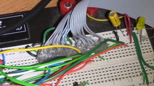
 A few days ago the stuff from New Haven Display got here and this weekend I wired it all up. The first task was to get the LCD wired into my breadboard. Items you need for this are 20-pin ribbon cable, a female connector, 20 pin header, and some hot glue. I’ve played with character LCDs before and developed a system to lead out the connectors to a breadboard. Separate and strip each wire of the 20-pin ribbon cable (I know, it’s not really fun) and solder it to the header. Then use the hot glue to hold the wires and make a strain relief and grip hold so you can plug it into the breadboard.
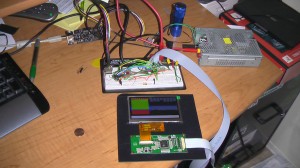
I have a few ATMega88A micros laying around and slapped one of those on the board to get something running. The SDD1963 controller makes it really easy to interface a micro with the LCD. There are only 8 data lines, 3 supply lines and 6 control lines. The ATMega88 has a full byte wide I/O port and a few partial I/O ports, so wiring the LCD up was no problem. For the curious, I used PortB for the data and PortC for the control lines, with a single line on bit 4 of PortD. Now with the setup done time for the software. Take a look at the setup, below
Software
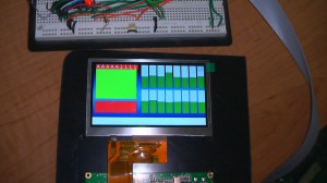
I use Ubuntu at home for my development and chose the ATMega because there is support in the GCC for the AVR and also support for the AVR Dragon programmer via avrdude. Just a note, I had problems with the version of avrdude that is for Ubuntu 9.10 so I use version 5.5. The setup of the LCD was easier than I thought, due to the app notes and code posted on the New Haven Display site. I used the config for the 5.7 inch display as a base and tweaked the command values to match the 480×272 size of the 4.3 inch. There are 16 batteries in the car I want to use this in, thus I need a way to show 16 values quickly. I played around with window drawing and make a simple bar graph function to show percentages on the display at arbitrary locations. The last thing I did was try and create text values on the screen. The reason I stopped here is the ATMega only has 8k flash and 1k RAM and I was hitting a memory limit when I tried to compile more than 2 letters. You can see the fruits of my labor in the picture below
I have zipped up the code and uploaded it here for all to use. This is a really fun little project to get your feet wet with TFT LCDs. There should be more updates as I upgrade to a better processor and design the hardware to go into the car. So check back for more soon!
CODE: ATMega88 code for New Haven Display 4.3 inch TFT LCD
S1axter
Other Links to this Post
-
ATMega88 and Color TFT LCD | myBitBox — May 4, 2010 @ 11:51 pm
-
Vehicle information display hacks - Hack a Day — May 5, 2010 @ 1:19 pm
-
Vehicle information display hacks | ThePcTool.com BLOG — May 6, 2010 @ 6:13 am


By Stu kennedy, May 6, 2010 @ 5:07 am
Brilliant write up, been looking for a tft to wotk with ATMega, Do you think i will have any probs with Arduino and the TFT?
By Patrick, July 2, 2010 @ 1:27 am
Hello S1axter,
After reading your post I have in mind to adapt the code to the atmega644p, which has much more memory onboard. Is it possible to share the pcb layout or pin-out / connections?
Thnx in advance
By Marcos, November 10, 2010 @ 4:17 pm
Echoing some of the other comments, this write up up was outstanding. And like some of the others I was curious about the pcb layout and pin connections. If you could share that or suggest how to go about it I’d really appreciate it.
By william, May 6, 2011 @ 12:38 am
LCD supplier